Week 2: Computer Aided Design
What should I do this week?
In this second week of Fab Academy, I have to model (Raster, Vector, 2D, 3D, Render, Animate, Simulate) a possible final project, compress the images and videos and post it in the website. The major tasks involved are:
- Model a part/ full model of my final project using various tools and find which fits me best
- Demonstrate various results using images and videos but in compressed format to save space
- I need to install various softwares and troubleshoot them if necessary
- Need to include orginal design files, analyze various parts if possible & explain my learnings in layman language
- Learn about difference betweeen Raster & Vector Images
The following are the softwares that I have used for learning various operations:
- Krita : Raster Images
- Inkscape : Vector Images
- Tinkercad : 3D Modelling (Test)
- Autodesk Fusion 360 : 3D Modelling, Rendering, Animation & Analysis
Week 2: Action Plan
| |
|
|---|---|
| Wednesday | Prof. Neil's class, Image & Video Compression |
| Thursday | Raster using Krita, Vector using Inkscape |
| Friday | 3D Modelling using Fusion 360 & Onshape |
| Saturday | Animation using Fusion 360 |
| Sunday | Rendering using Fusion 360 |
| Monday | Simulation on Fusion 360, Sim Scale Testing |
| Tuesday | Documentation & Local Review |
Raster & Vector
Normally vector images are composed of paths, which are normally represented using mathematical functions. These mathematical function represents the actual borders and the different elements in the image. Hence the maximum resolution of the image is not limited by the number of pixels. These mathematical functions can scale easily giving lossless ability to zoom to any extent on the image. Raster image is made up of individual pixels. Each pixel contains only one colour and is arranged in a certain fashion to make up the image. This is how normal pictures are displayed. The problem with raster image is that the maximum resolution is limited by the number of pixels. That means, when you try and scale the image into a larger size, the quality drops and the edges of lines become fuzzy. The differences between the two are further explained below:
| |
|
|---|---|
| They are composed of pixels | They are composed of paths |
| They occupy more space | They occupy less space |
| They loses quality when scaled up to larger sizes | Scalable without loosing quality |
| Good at displaying large number of colors | Poor at displaying large number of colours |
| Formats: JPG, BMP, TIF etc. | Formats: SVG, CGM |

Vector vs Raster (Image credits: Retronator Magazine)
Raster creation & editing using Krita
Krita is a free and open source raster graphics software which is designed primarily for digital painting and 2D animation. To be frank, it was my first time hearing about Raster graphics and Krita so I my main goal was to get familiar with various tools offered by Krita. At the first glance, I was shocked since I thought that it would be similar to Microsoft Paint but was amazed to find that the software was mainly used for artistic works and is not simple as it seems. Before Krita I also tried GIMP but I found Krita to be more user friendly for my liking. Unlike everyone, who was busy making meeme using raster softwares, I wanted to experiment something related to my project using Krita. An idea about a spinning wheel came to my mind which can be attached to the top of the cloth dryer (final project) which would once engage the user while their cloth is being dried.The following steps will explain how I made spinning wheel using Krita:
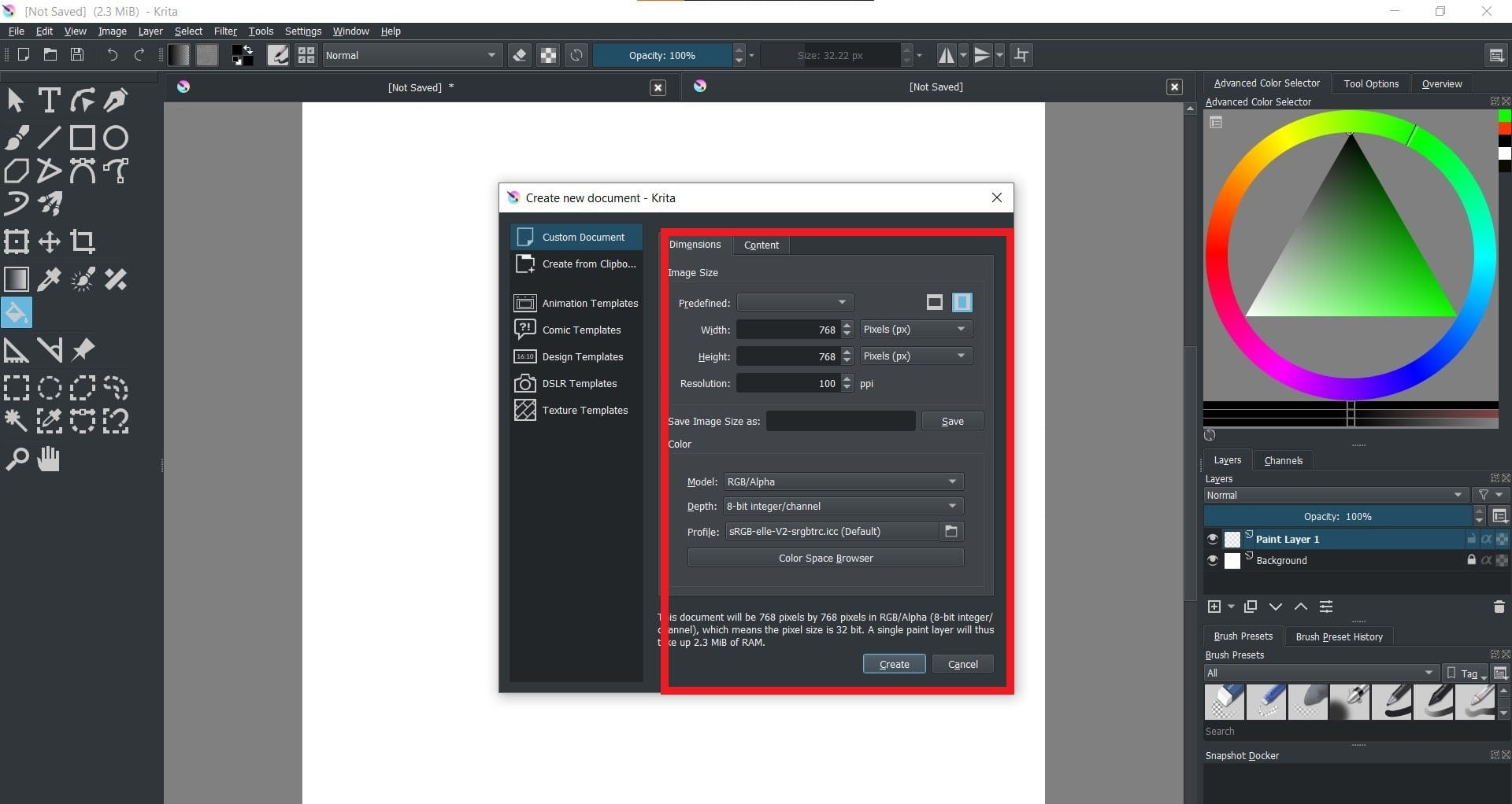
1. At first I had created a new document while selecting a resolution that is optimized for the website.
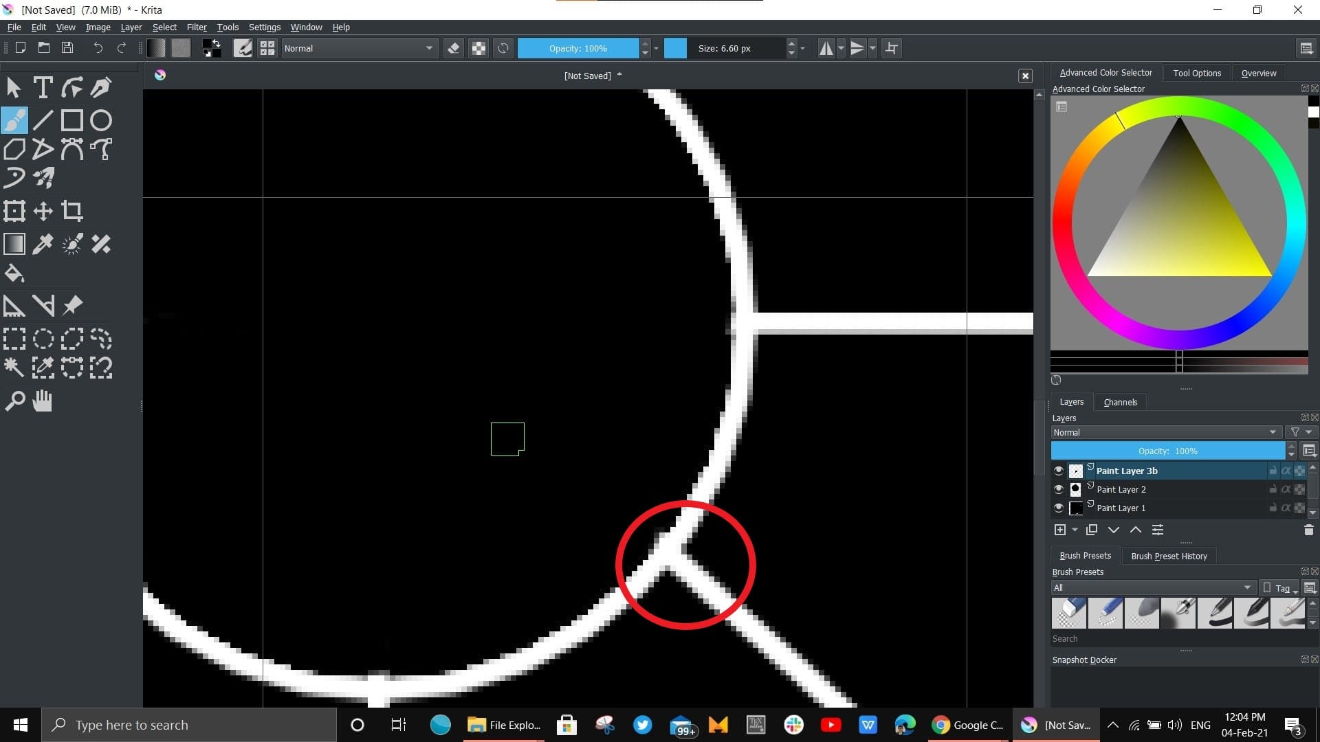
2. A basic outline of the spinning wheel was made and the image was zoomed to check how pixalated the image was (thereby confirming Raster Graphics)
3. Here comes the first mistake, unknowingly I tried to manually color the sectors and my instructor Mr. Jogin introduced me the layer and fill colour tool thereby making my work much easier and cleaner.
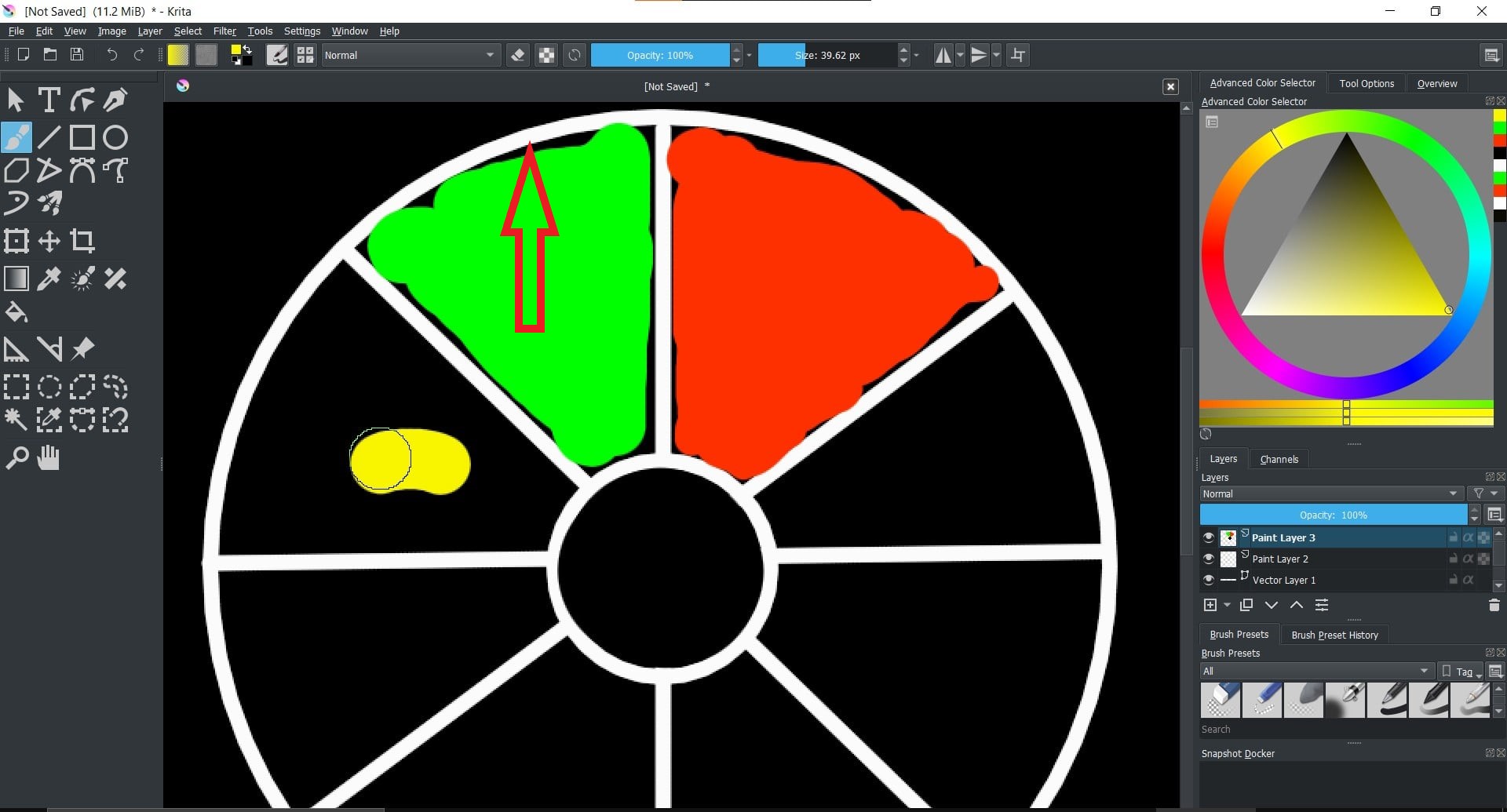
4. This image shows the various layers and the fill tool used to create perfect colored sectors
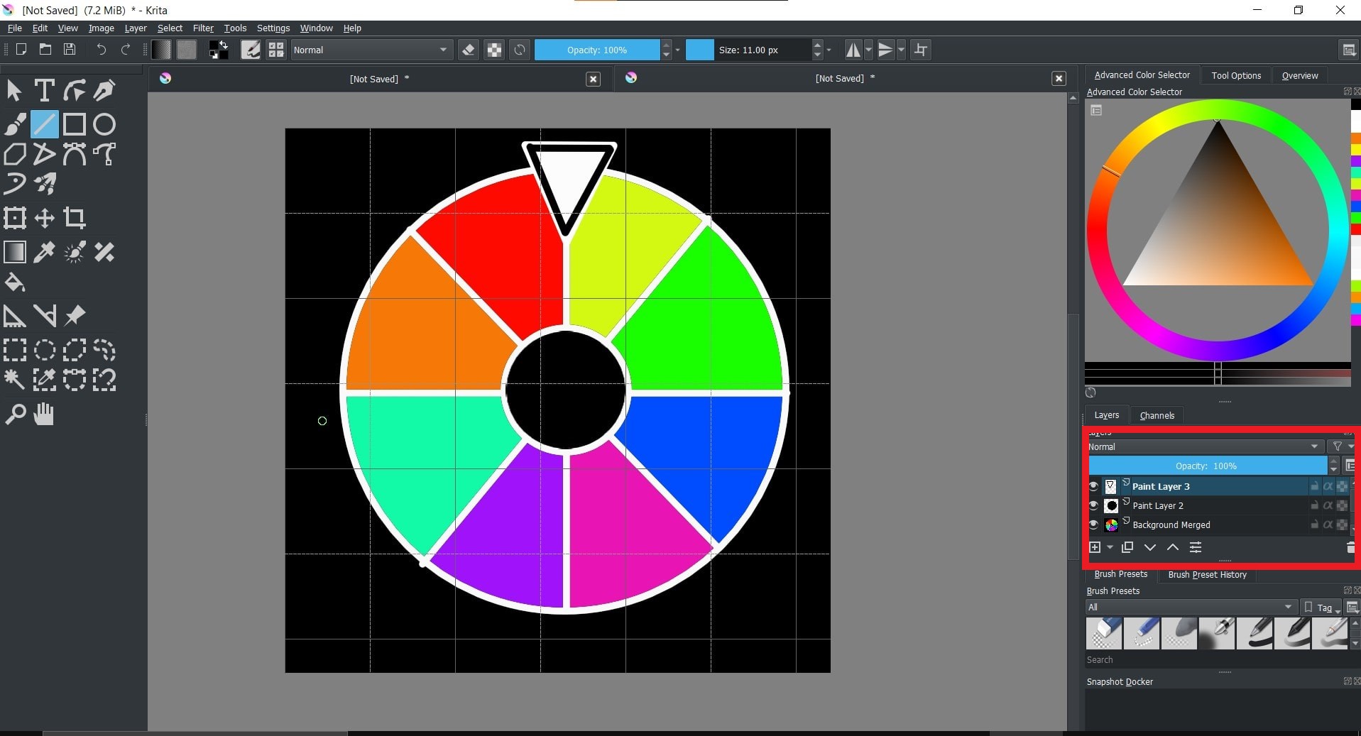
5. Finally, text was placed at various sectors and the wheel is completed
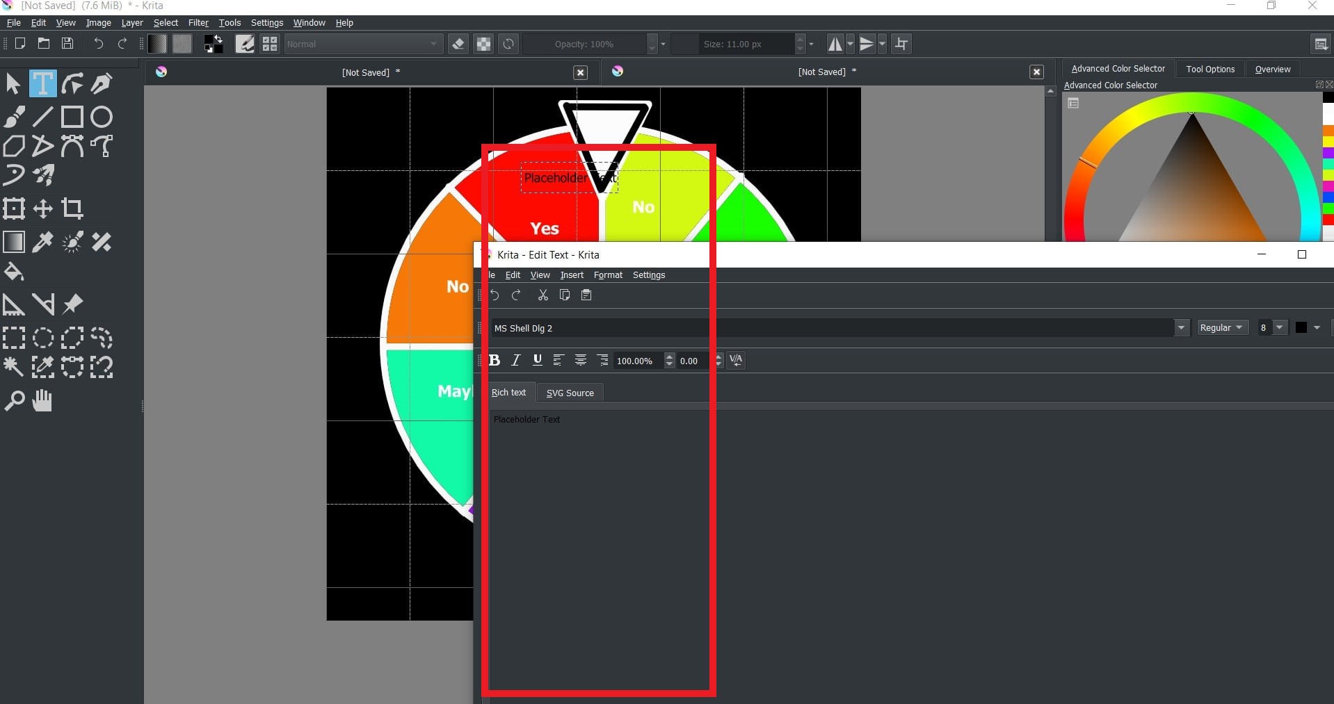
6. This is the final spinning wheel sticker that I am planning to fix on the top side of cloth dryer using Vinyl Cutting
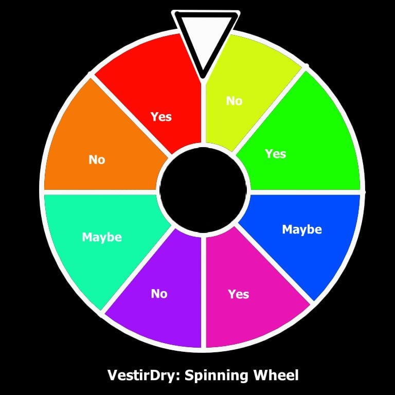
7. The output images were saved and combined together online using GIF Maker and ouput is as follows

Inkscape: The Vector based editor (a.k.a timesaver for me)
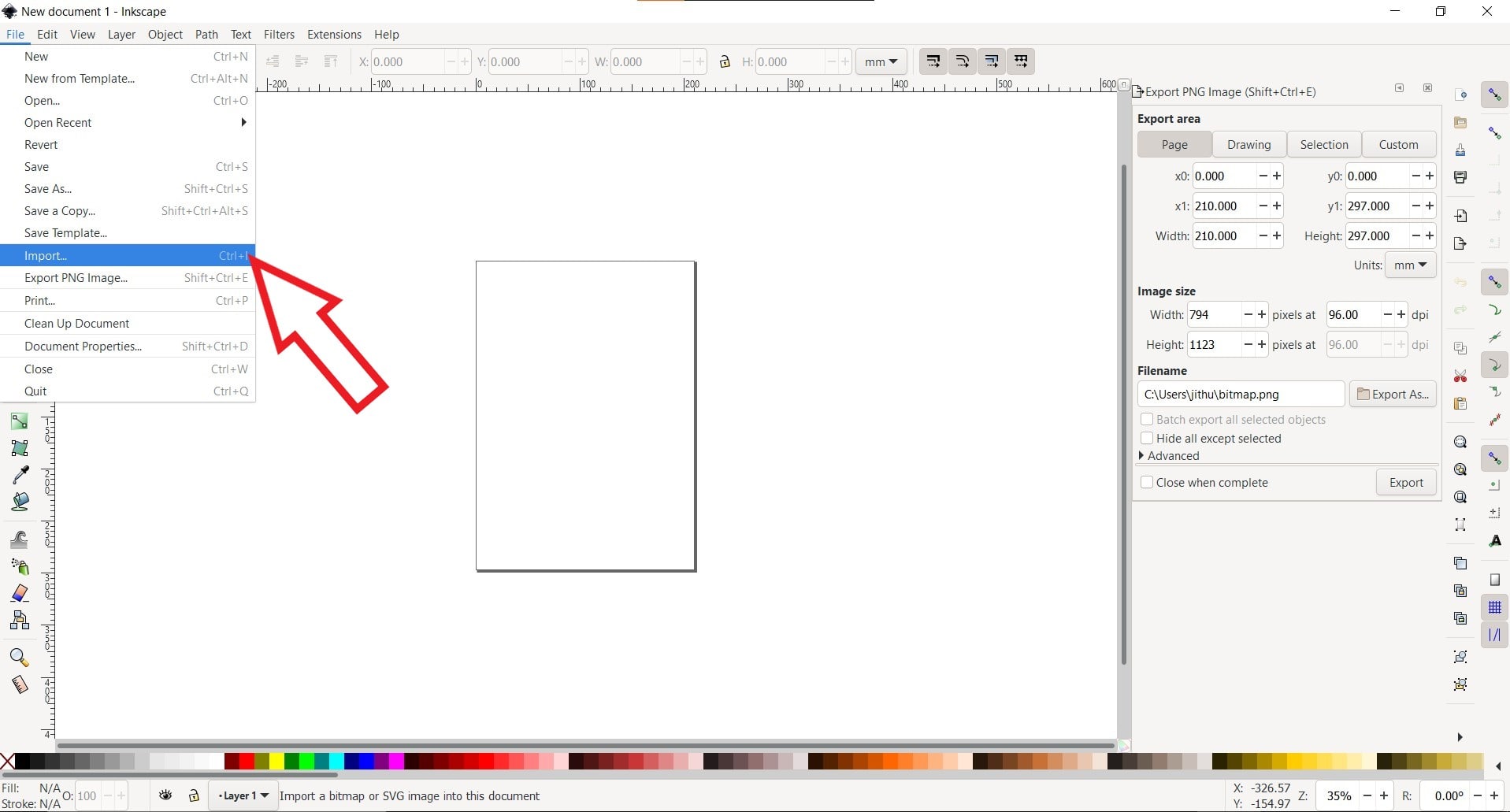
Inkscape is a free and open-source vector graphics editor. It can be used to create or edit vector graphics such as illustrations, diagrams, line arts, charts, logos and complex paintings. Inkscape's primary vector graphics format is Scalable Vector Graphics (SVG), however many other formats can be imported and exported. I prefered this software since it's user friendly and can be used in future for tracing bitmap for providing input to various machines. Initally I thought of replicating what I had done in Krita in Inkspace inorder to check the difference in quality while zooming but later I thought of making a logo for my final project. Coming to the logo making, first of all I had imported an image from the web (Credits: Logo Ground) that contains the symbol of a fan throwing the air omnidirectionally (similar to what my cloth drier does). Then I need to convert that raster image to vector and then modify it for my purpose. The steps are mentioned below:
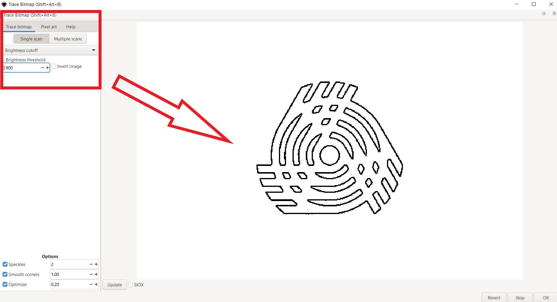
The next step was to trace the bitmap by going into
Path-> Trace Bitmap
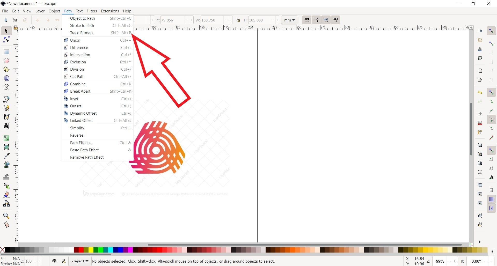
The values of various thresholds are adjusted and the most optimized setting is selected based on the output
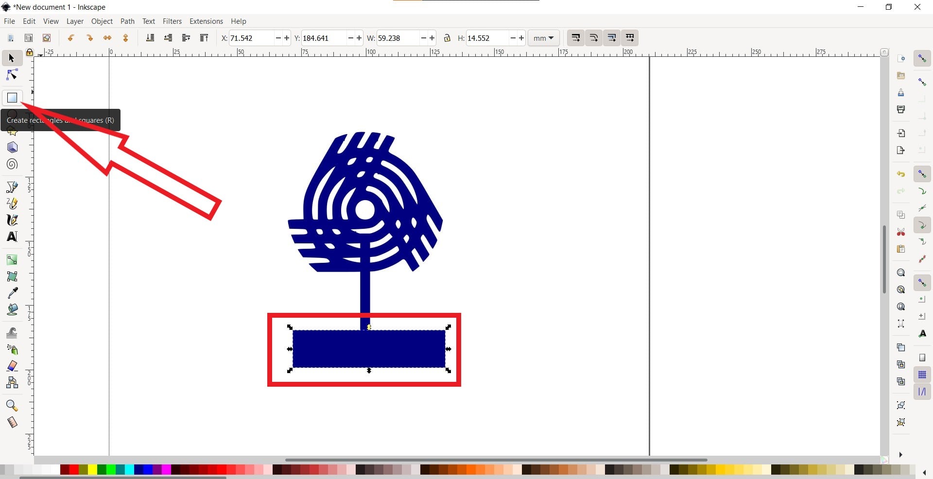
Next, I have added the required color using the fill tool and add 2D shapes for my custom logo
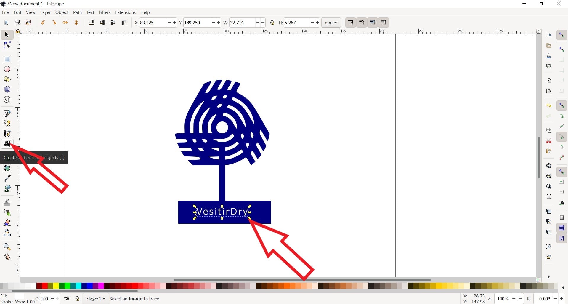
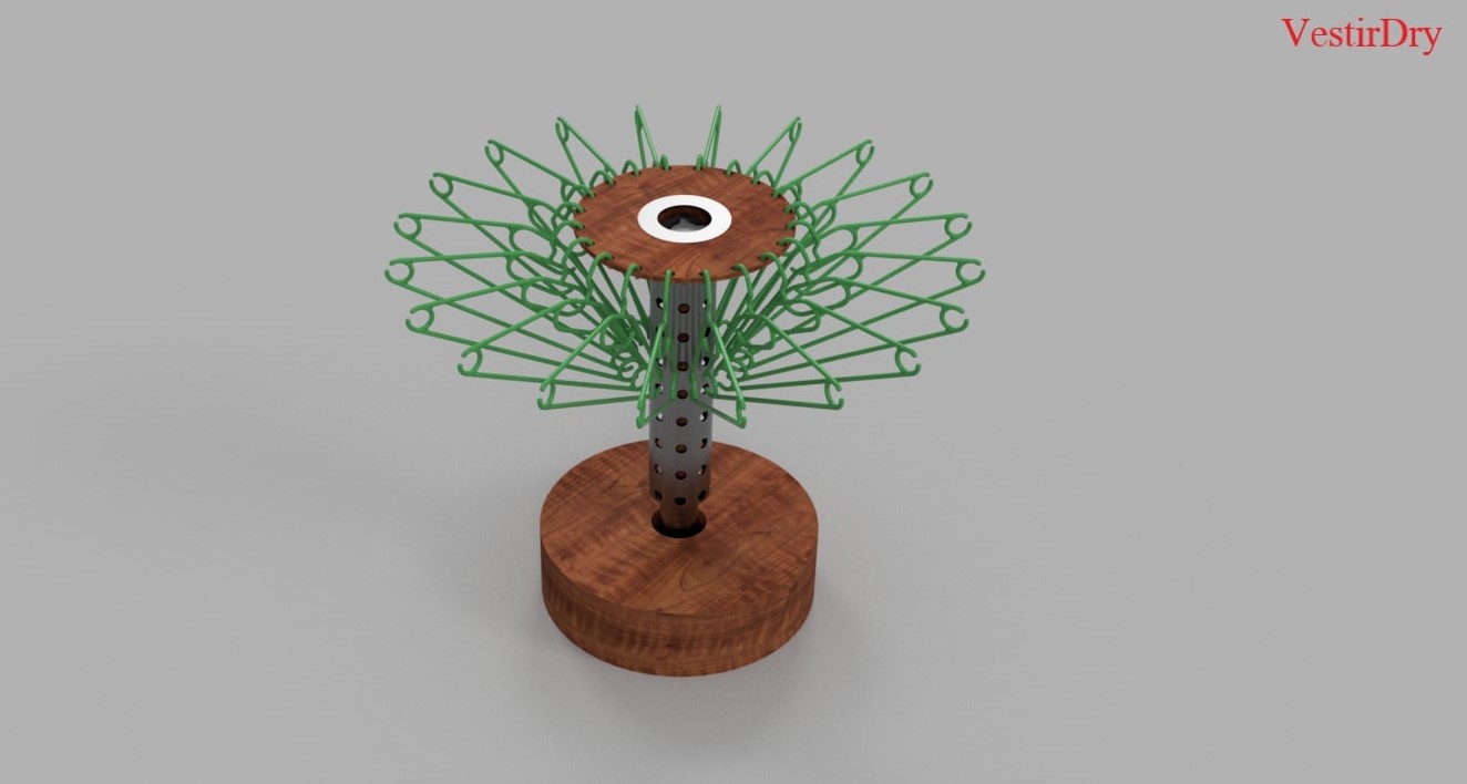
Finally the text was added and I had named the final project as "VestirDry" (Cloth Dryer in Spanish)
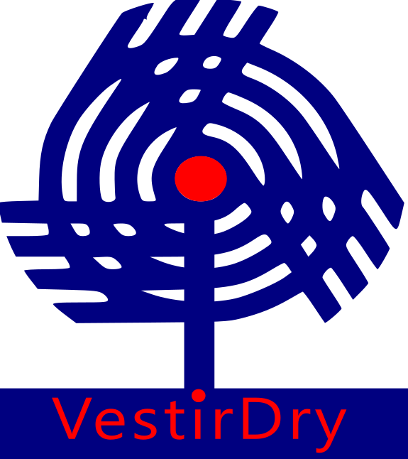
This is the final logo that I had made using Inkscape for my final project
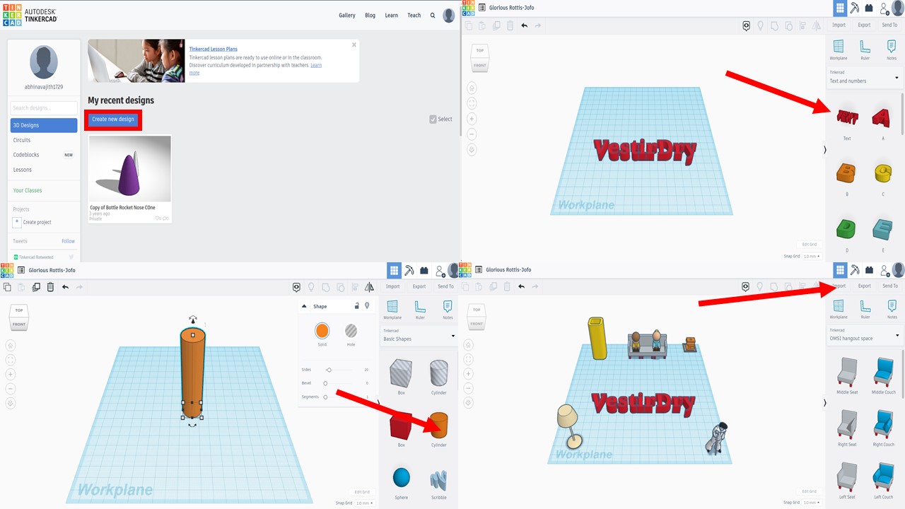
Tinkercad: 3D Modelling
Tinkercad is a free, online 3D modeling program that runs in a web browser, known for its simplicity and ease of use. Since I am proficient with SolidWorks, I hard chosen this platform to try how it was. The interface is quite simple but I felt there were limited options only. The process of creating a model is quite simple : just create a new project, add elements from the inbuilt library, resize & position it depending upon the need & finally export it as STL/OBJ depending upon our used Here are some trials that I had conducted using Tinkercad:
Autodesk Fusion 360: 3D Modelling, Rendering, Animation & Analysis
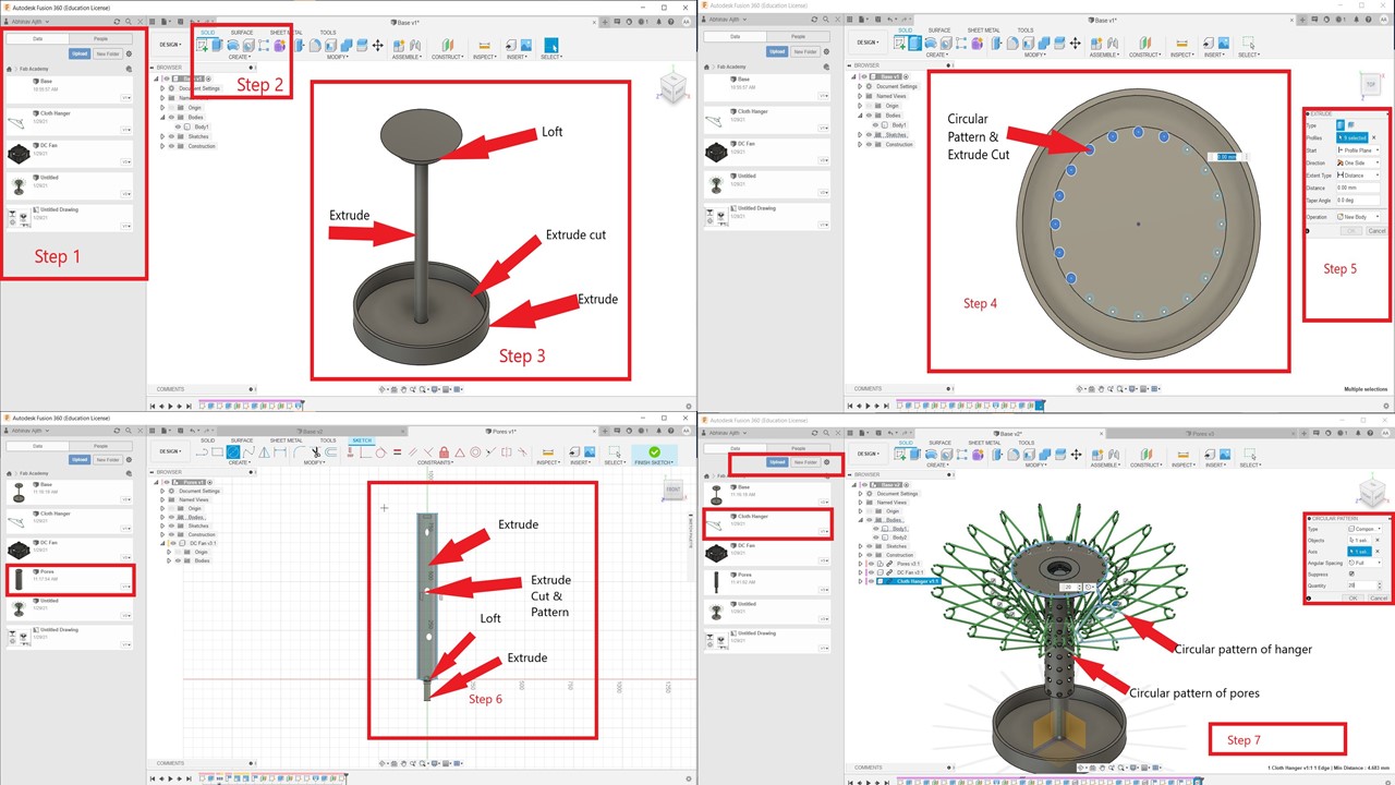
Fusion 360 CAD/CAM software connects your entire product design & development process in a single tool. It works on a cloud based server and Fusion is said to have one of the best virtual collaborative work spaces. Since I am a mechanical engineer by profession, I already knew many designing softwares like Fusion 360, SolidWorks, Catia etc. and I chose Fusion 360 since it's very easy to use as well as the Fab Lab Kochi recommmends using it due to the collaborative environment which helps the instructors to correct on the go. Here are the steps involved in creating a 3D model using Fusion 360:
- I have opened Fusion 360 and created a new folder in cloud named "Fab Academy". This is used to save various components in a single folder which can be access easily anywhere
- The next step is to draw various strucutures of the model using basic shapes like circle and need to extrude them to make a 3D shape. For creating the top part two circles in created in seperate planes and is connected using "Loft" command.
- Next, a circle is drawn on surface of the top layer and a circular pattern is created depending upon the need. Further, the circles are selected and is extruded to create holes which is used for hanging
- Now, I need to make the stem which includes the pores as a seperate component and need to add to main part as an assembly. Operations like extrude, loft are used to create the basic structure. Further, extrude cut operation is used to create pores which is similar to what I had done in the case of hanger slots
- Finally, I had imported a hanger component and a NIMA stepper motor and a DC fan to complete the model. I had used GrabCAD for this purpose
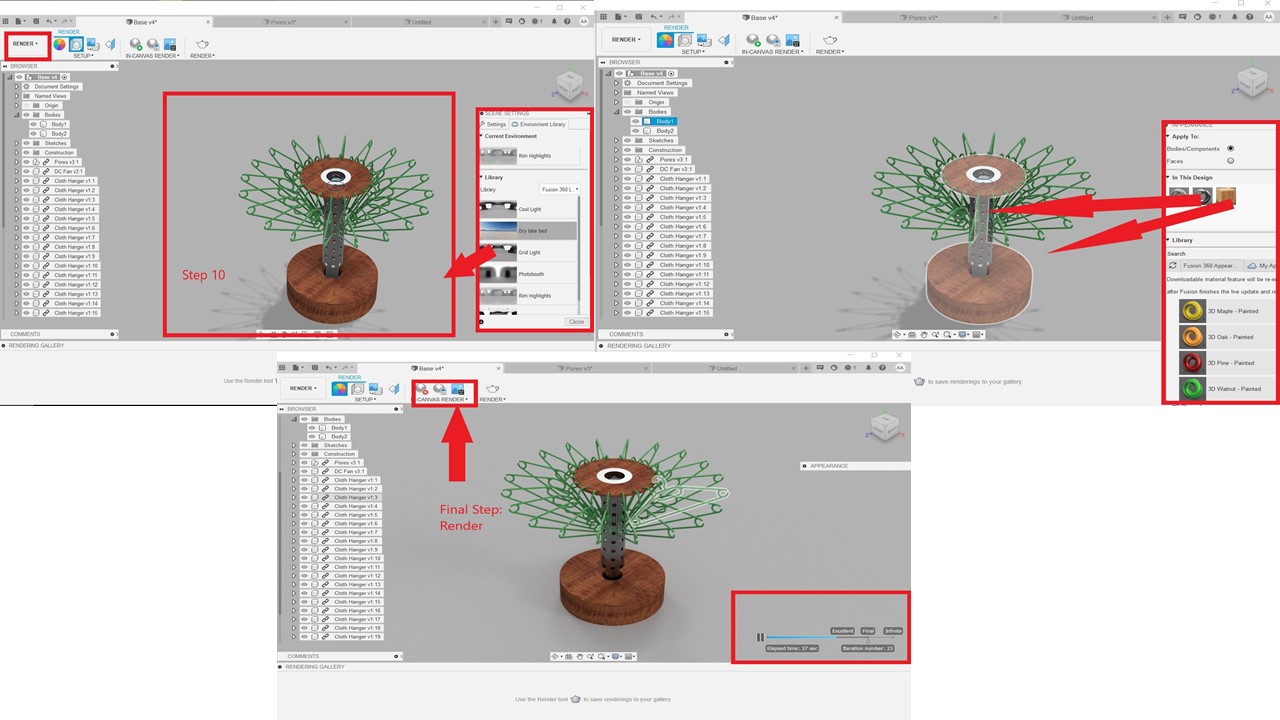
Rendering the model using Fusion 360
- For rendering the model, I need to change from design to render in the menu bar. Next I need to click the scene settings and choose an appropriate background or can even import an image to choose as the background
- Now, I need to choose the appearance tab and need to select appropriate materials for various parts. In this model, I had used Cherry Wood, Steel and ABS for various parts
- The next step is to select the in canvas render and need to select the quality. I had choosen Final as I need to create a compressed image for the website
Creating drawings using Fusion 360
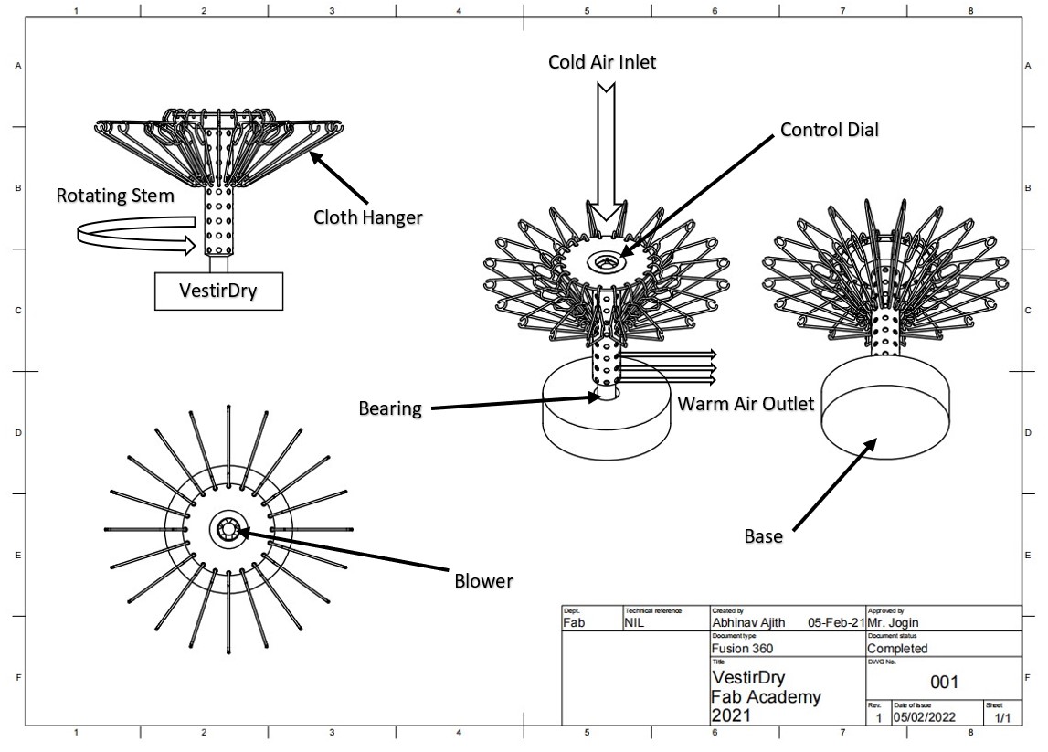
For this step, I need to change the mode from render to drawing in the menu bar. Next I need to place various views of the model ie. Front, Top, Isometric in various locations. Then I have saved the image as PDF and then had taken a screenshot to reduce the size. Further I had imported the image to Microsoft Word and had used basic shapes and text box to annotate various parts of the model. The drawing is depicted as follows:
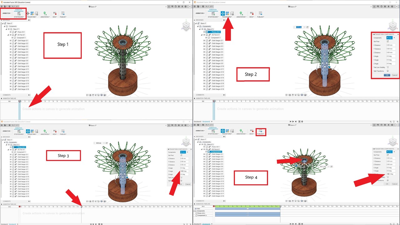
Animation using Autodesk Fusion 360
An working video of the project would help the visitor is understand the idea better. So I tried to create an animated video of VestiDry using the inbuild animation tool present in Fusion 360 First, I have to change from design tools to animation tools from menu bar. Then I need to place the cursor to the start of animation timeline and must click the tranformation tool under animation. Since the velocity of fan and the tube with pores are different I have to seperately select both and provide the reqired angle of rotation. The velocity can be controlled by increasing the angle of rotation. The final angle is fixed by moving the curson to the required time stamp. Once the animation process is completed, it's exported using the publish command to required location.
Simulation using Fusion 360
Okay, so why should I add a simulation to the model. To be frank, I wanted to create the flow simulation of air inside the tube with pores but I couldn't do it due to lack of CFD tools in Fusion 360. Since, I had replaced the harddisk of my PC, I had lost the Ansys student version so I searched for better alternatives to conduct the simulation. An online CFD tool called Sim Scale was found to be the best fit, and I even tried a couple of times to simulate the air flow using Sim Scale but failed. I had introspected and found that the problem maybe due to lack of tutorials on how to use SimScale or it maybe due to the error in process of simulation (I am the culprit here). Anyway, I will try to do the same in Ansys when I have access to it. In the meantime, I thought of a simple static simulation experiments to test the material strenght of various cloth hangers. For that, I had chose a PET cloth hanger and an iron cloth hanger. My goal is to find out the displacement in each of them when I apply the same load ( ie the weight of the cloth). For this experiment, I haven't referred to any online material and I am on my own. The following are the steps involved in performing a static analysis in Fusion 360:
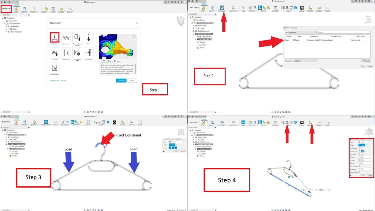
- The first step is to switch the mode from design to simulation in menu tab. Then I have created a new simulation
- Now, I need to ensure that I had chosen the right material by going into material tab. I plan to use PET for first cloth hanger and iron for the second analysis
- The next step is to apply the fixed constraint by clicking the option and here the hook portion is the fixed part, further the load is given in each arms.
- For realistic results, I had provided a 1kg load on the arms (9.81N) and had started the analysis
- Similary, I had repeated the same procedures for the iron hanger and received satisfactory results
Even though the results seems obvious, I reconfirmed the following data:
| |
|
|---|---|
| Safety Factor (Min) = 7.418 | Safety Factor (Min) = 15 |
| Max Stress = 7.334 MPa | Max Stress = 7.288 MPa |
| Max Displacement: 4.46 mm | Max Displacement: 0.07393 mm |
| Max Strain: 0.004016 | Max Strain: 0.00005968 |
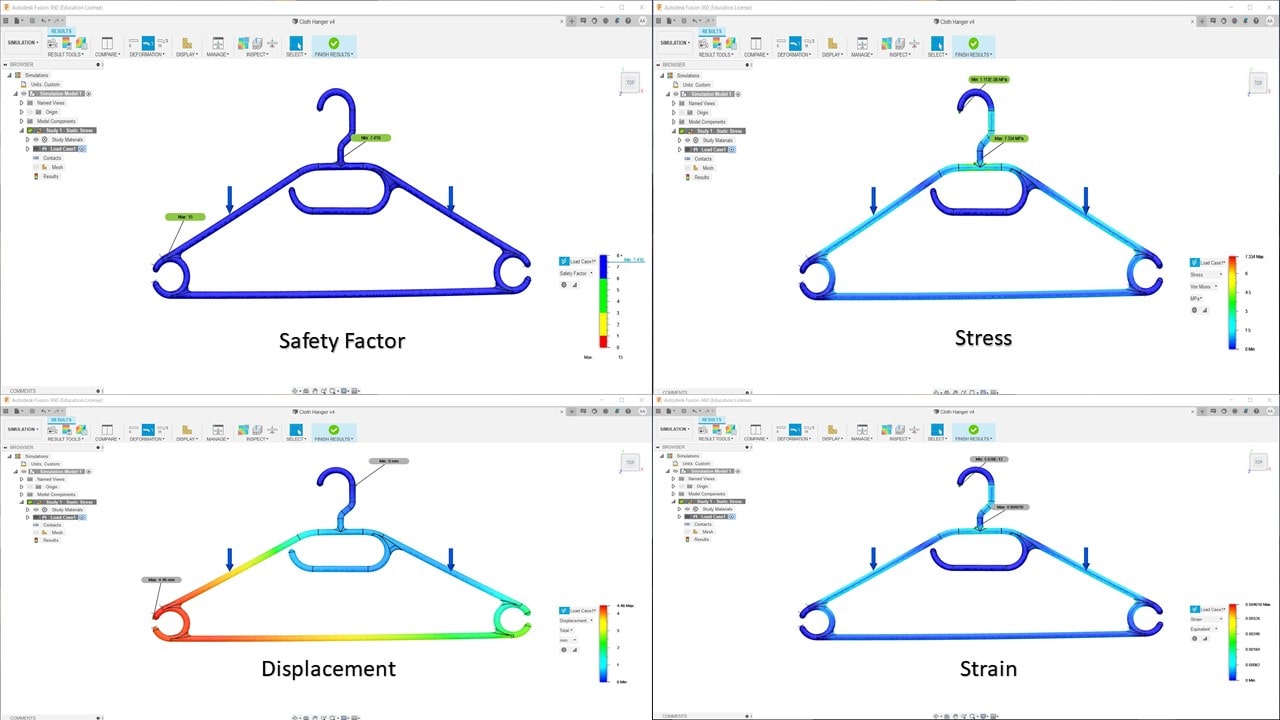
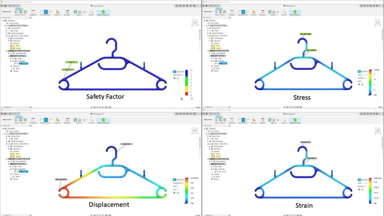
The results reconfirm the fact that the iron cloth hangers are far stronger than PET based cloth hangers and would be a better choice for the project.